Waveguide Filters
FREQUENCY RANGE: 2 GHz to 40 GHz
- BANDPASS, LOWPASS OR NOTCH CCONFIGURATIONS
- PROVIDES FOR LOWER INSERTION LOSS
- GOOD FOR HIGH POWER REQUIREMENTS
- WAVEGUIDE OR COAXIAL INTERFACE
Waveguide filters can be used in the frequency 2 GHz to and excess of 40 GHz Waveguide can support an infinite number of field patterns, each with a different guide wavelength. The normal mode used is the dominant TE in rectangular waveguide, although other configurations are used for special applications.
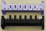
RECTANGULAR WAVEGUIDE FILTERS
hese can have lowpass or bandstop characteristics. Lowpass filters are formed by means of a corrugated wavelength structure with adjacent high and low impedance sections.
The normal construction for bandpass filters is to place inductive obstacles, typically an array of posts, along a waveguide at spacings close to a half wavelength apart. The size, number and transverse spacings for the posts are the parameters that vary the filter bandwidth while the longitudinal spacing determines the center frequency of the filter.
Bandstop filters can be made by placing short-circuited cavities approximately a quarter wavelength apart along the filter body.
The major advantages of waveguide filters are high power handling and low-loss performance. Waveguide filters are fabricated in aluminum, brass, copper and Invar. Materials are selected to ensure that the lowest possible passband insertion losses are achieved. The advantage of Invar construction is its low thermal expansion, which provides optimum temperature stability. Aluminum construction is best suited where weight is of major importance. All filters have tuning screws that are locked and sealed with epoxy.
The interface is normally in the appropriate waveguide size. However, for most types, integral coaxial transitions on one or both ports are available as options.