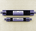
Tubular Filters
FREQUENCY RANGE: 20 MHz to 12 GHz
- NUMBER OF SECTIONS AVAILABLE: 2 TO 15
- PROVIDE FOR INCREASED POWER HANDLING CAPABILITY
KW Microwave offers tubular filters in highpass, lowpass and bandpass configurations.
Standard sizes of tubular filters range from .250 inch to 1.250 inches in diameter. Tubular lowpass filters cover the frequency range of 20 MHz to 12 GHz KWM Tubular filters are Chebyschev design and are available in 2 to 12 sections. Four different sizes and frequency ranges permit the proper sections to achieve an optimized design.
Almost any type of input and/or output connector is available as a standard item. Bandpass filters are designed with resonating sections. Each section is capacitively coupled to provide the specified passband response and selectivity required. This coupling structure provides a DC Block.
LOWPASS FILTERS
KW Microwave offers different sizes of lowpass tubular filters. Sizes range from .375 diameter to 1.250 diameter depending upon the frequency and other electrical characteristics. Low-pass filters cover the frequency spectrum of 15 MHz to 12GHz KWM’s tubular filters are of Chebyschev design and are available with the number of sections equaling 3 to 15 sections. Four different sizes and frequency ranges allow for the selection of an optimal design for each requirement. Almost any type of input and/or output connector is available as a standard item.
BANDPASS FILTERS
Bandpass filters are similar to the lowpass filters in size and frequency and range availability. Each section is capacitively coupled to provide the specified passband response and selectivity required. This coupling structure provides a DC Block.
INSERTION LOSS
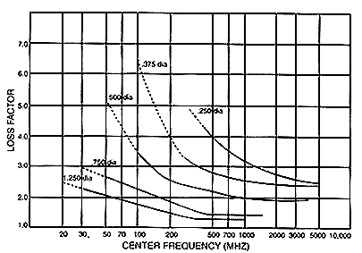
The maximum insertion loss at center frequency is equal to:
((LF x (N= .5) ) / % 3dB BW ) + 0.2
Where:
LF= Loss Factor, N= Number of Sections, % 3dB BW= 3dB BW (MHz) x 100
An example:
A 3 section SM with a center frequency of 400 MHz and a 3dB BW of 40 MHz would have:
(3.0 x 3.5)/10 = (10.5/10) = 1.05
1.05 + .2 = 1.3 dB
Sepecifications
| SERIES | |||||
| 1.250 dia | .750 dia | .500 dia | .375 dia | .250 dia | |
| ELECTRICAL | |||||
|---|---|---|---|---|---|
| Center Frequency (Fc, MHz) | 20-1000 | 30-1500 | 50-4000 | 100-5000 | 300-120000 |
| 3 dB Relative Bandwidth (% of Fc) | 2-40 | 2-40 | 2-40 | 2-40 | 2-30 |
| Number of Sections Available | 3-8 | ||||
| Number of Maximum Insertion Loss | See Curve Below | ||||
| Maximum VSWR | 1.5 | ||||
| ENVIRONMENTAL | |||||
| Shock | 15G | 15G | 30G | 30G | 30G |
| Vibration | 5G | 5G | 10G | 10G | 10G |
| Relative-Humidity | 90% | ||||
| Temperature – Operating (C) | -25 to +70 | ||||
| Temperature – Non-Operating | -54 to +85 | ||||
| MECHANICAL | |||||
| Diameter (inches) (mm) | 1.25 (31.7) | 0.75 (19) | 0.5 (12.7) | 0.375 (9.5) | 0.25 (6.4) |
| Approximate Weight (oz per inch) | 1.25 | 0.75 | 0.75 | 0.5 | 0.375 |
