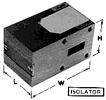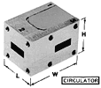
Circulators and Isolators – Broad Band
| Band | Frequency (GHz) | Isolation (dB Min) | Ins Loss (dB Max) | VSWR (Bilateral Max) | Flange Type | Weight (Oz) | L” | W” | H” | Model No. |
| X | 8.20-12.40 | 20 | 0.50 | 1.20:1 | UG | 10 | 1.750 | 2.25 | 1.63 | 100XC |
| 135/U | 12 | 1.750 | 3.25 | 1.63 | 100XI | |||||
| P | 12.40-18.00 | 18 | 0.50 | 1.30:1 | UG | 9.0 | 1.312 | 1.75 | 1.32 | 100PC |
| 1665/U | 11 | 1.312 | 2.50 | 1.32 | 100PI | |||||
| K | 18.00-26.5 | 16 | 0.50 | 1.35:1 | UG | 3.0 | 1.000 | 1.25 | 1.25 | 100KC |
| 597/U | 3.5 | 1.000 | 1.75 | 1.25 | 100KI | |||||
| R | 26.50-31.50 | 18 | 0.50 | 1.30:1 | UG/ | 1.5 | 0.750 | 1.00 | 0.80 | 100RC |
| 599/U | 2.0 | 0.750 | 1.50 | 0.80 | 100RI | |||||
| R | 29.50-34.00 | 18 | 0.50 | 1.30:1 | UG/ | 1.5 | 0.750 | 1.00 | 0.80 | 101RC |
| 599/U | 2.0 | 0.750 | 1.50 | 0.80 | 101RI | |||||
| R | 31.50-36.00 | 18 | 0.50 | 1.30:1 | UG/ | 1.5 | 0.750 | 1.00 | 0.80 | 102RC |
| 599/U | 2.0 | 0.750 | 1.50 | 0.80 | 102RI | |||||
| R | 34.00-38.00 | 18 | 0.50 | 1.30:1 | UG/ | 1.5 | 0.750 | 1.00 | 0.80 | 103RC |
| 599/U | 2.0 | 0.750 | 1.50 | 0.80 | 103RI | |||||
| R | 36.00-40.00 | 18 | 0.50 | 1.30:1 | UG/ | 1.5 | 0.750 | 1.00 | 0.80 | 104RC |
| 599/U | 2.0 | 0.750 | 1.50 | 0.80 | 104RI |
Notes:

- RF Power: 1 kW Peak typical all units; 10W Average at X and P Band with 5 W Average at K and R Band.
- Temperature Range: -40 to +85 (C) Typical
- Flange Holes: UNC – 2B threads, standard.
- Flange Thread Option: Non-locking steel inserts, add suffix “H” to Model Number. (I.e. 100RIH)